Analog Gauge
The analog gauge is the simplest way to display the real-time value of analog signals or floating point and integer variables.
Description
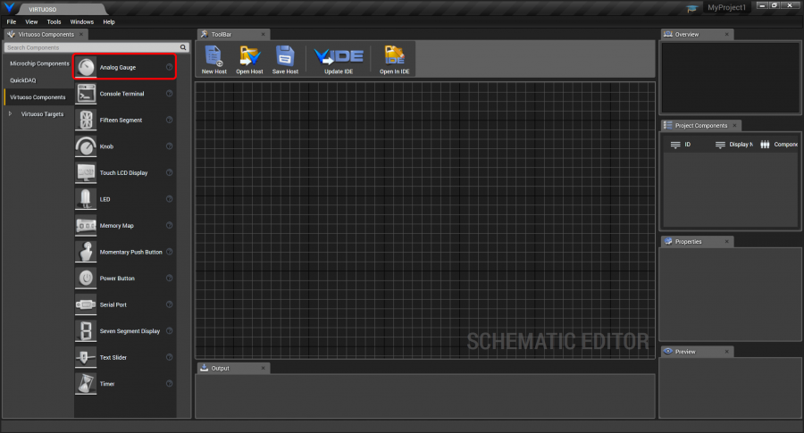
To use an analog gauge, drag and drop it from the Virtuoso Components control group onto the schematic, or right-click the schematic area and type “gauge” and select the analog gauge from the drop-down.
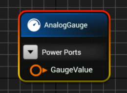
The analog gauge has a single GaugeValue double precision input port.
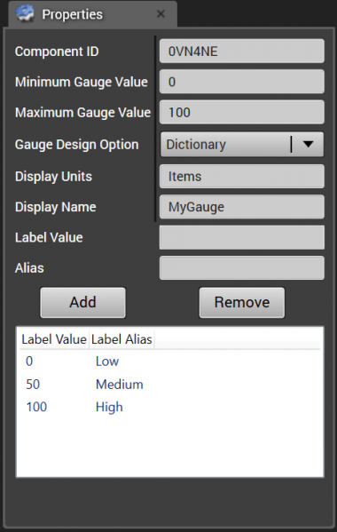
The analog gauge’s properties are shown below.
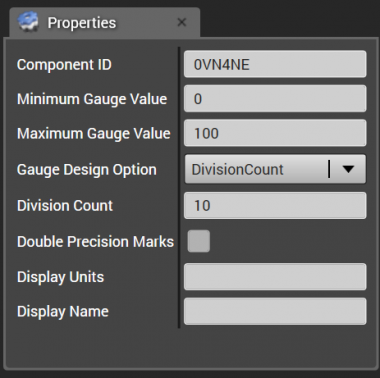
The Component ID is generated randomly when the gauge instance is created.
The Minimum and Maximum Gauge Values indicate the range of values that the gauge will display.
The Gauge Design Option determines how the ticks will be arranged along the gauge to indicate the gauge’s value. The DivisionCount option evenly divides the gauge’s display angular range into the specified number of evenly distributed steps, as indicated in the “Division Count” input. The value at that position is displayed on the mark, as determined by the minimum and maximum gauge values, and the division count.
The List option allows a list of string labels to be used to indicate the value along the gauge. The labels are evenly distributed along the range, so the first label in the list will correspond to the gauge minimum value, and the last label will correspond to the gauge maximum value. Labels between the first and last will be evenly distributed along the gauge.
The Dictionary option allows labeled ticks to be individually positioned arbitrarily. To add a tick, you just specify a tick position and tick label. The label with its tick will be displayed at the specified position.
[ToDo: Show result]
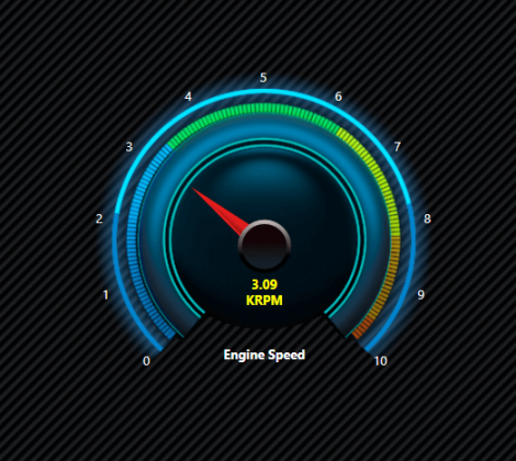
The Display Units text is shown beneath the value that is displayed inside the gauge. The Display Name, if desired, is displayed below the gauge. The image below shows the gauge with Display Units of KRPM and Display Name of “Engine Speed”.
The Double Precision checkbox determines whether the gauge will display the value as a double precision value or integer.
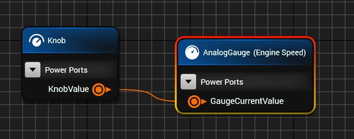
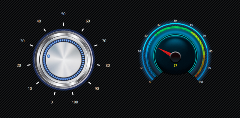
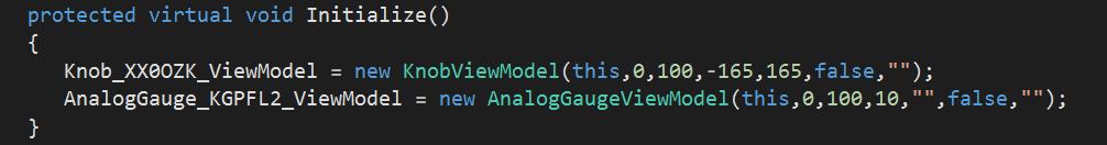
To easily see how the gauge works, connect a knob to control the gauge value as shown below. Both the knob and gauge can have a range of 0 to 100. When you run the host, you will be able to control the gauge value by moving the knob. Since the knob and the gauge are both double precision ports, conversion isn’t needed, however if another port type, like a 32-bit integer, is connected to the gauge, the integer will be converted to a double by the port connection snippet metadata.
The XAML code emitted for the knob and gauge for a C# WPF host are as shown below, with the data context for each binding to their respective view models.

The emitted base view model code regions are shown below. The knob and gauge view model properties are declared.
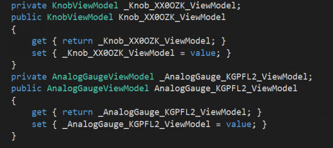
The emitted base view model code regions are shown below. The knob and gauge view model properties are declared
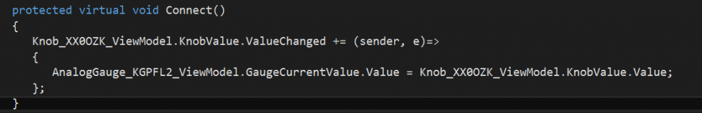
The port connection results in the Knob value’s change notification causing the gauge value to be updated with the knob value.