Variable binding allows statically linked variables (non-stack and non-allocated variables) or buffers of fixed length in memory to be exposed to C# to be used by the target host. A separate form of interfacing is needed in the case where data flows continuously, such as A/D converters and serial data streams. Virtuoso provides what are called Virtuoso Streams to easily support this capability. A Stream is simply a logical flow of continuous serial data, and both the target and the host participate in sharing data using Streams. Virtuoso does all of the hard work of passing the stream data between the target and the host application. The Virtuoso Target Model Builder is used to create a stream and define a name and direction for the stream, and a stream component is then added to the Target Model. The stream can be either an “UpStream” or a “DownStream”, depending on whether the data is flowing “Up” to the host or “down” to the target, respectively. If an upstream is created to send data from the target to the host, the Virtuoso UpStream component is added to the Target Model and available for the host to receive the data. If a downstream is created to send data to the target from the host, a DownStream component is added.
On the C# host side, sending data to the target in a DownStream is as simple as calling a function on the downstream C# component, which is available on the Target Model automatically when declared in the Target Model Builder. On the target side, the only thing that is needed for the target to receive the data is for a function call to be implemented to accept and process the data. This function is selected by the user in the DownStream configuration in the Target Model Builder. When the virtual device is then run, the host application can simply call a function on the downstream component to send data, and the function inside the target will be called to provide the data, much like an interrupt service routine.
When the user configures an UpStream component, the component is again added as a property of the Target Model, and the UpStream component’s DataReceived event is fired any time the target has sent data. So, to access this stream, the host application can simply subscribe an event handler to the UpStream component’s DataReceived event. To send data from the target to the host, a library is provided with a function to specify the stream handle and the data to be sent. The target application code simply needs to call the function and pass in the data, and it will show up on the Target Model’s UpStream component event.
The details of how the Upstream Library is incorporated into the target application, and how the target application is configured to be controlled by Virtuoso will be discussed shortly, however at this point the foundational concepts of how Virtuoso works should be in place. There is a target application written in C/C++, which is intended to run essentially identically to how it runs in its final deployment, and there is a host application, for example a C#/.NET application, which is written to interface with the target application while it runs. All interfacing between the host application and target application is done through a Target Model C# class, and this class is rendered/emitted by Virtuoso using the Target Model Builder. The user can select any variable to be exposed as a property on the Target Model, and the properties will be rendered by Virtuoso. Streams are also configured by the user, and these streams are also added as component properties on the Target Model.
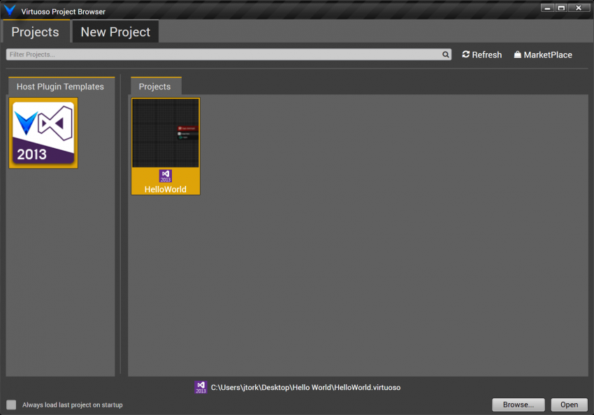
Open the HelloWorld host solution created in the Variable Binding section, by double-clicking the Virtuoso desktop icon, then double-clicking on the “Hello World” project, then when the schematic editor opens click on the “Open In IDE” button.
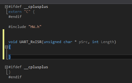
We will now create a “Down Stream” to allow C# host application code to write data to the target. First, in the “SimDriver” folder in the Target project, open the file “SIM_HW.c”. This is the default target C file containing virtual driver implementations for the “HW.h” hardware abstraction layer. Create a UART receive ISR function as shown below, with an unsigned char pointer argument and an integer data length argument.
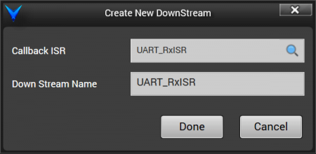
Now build the project, so that the UART_RxISR is compiled into the target and available to the Target Model Builder. Then open the Target Model Builder utility by double-clicking on the virtuoso target file “Target.virtuosotarget” in the Solution Explorer window. Click on the “Down Streams” tab, and click “New” to create a new down stream. In the Callback ISR textbox, start typing “UA…” and you will see the UART_RxISR function shown in the filtered function list. Select UART_RxISR, and the “Down Stream Name” field will automatically be populated with “UART_RxISR”, as shown below. Click Done.
Now close the Target Model Builder window, and go to the TargetModel.cs file. You will notice a UART_RxISR stream consumer interface property has been added to the target model, as shown below.

When the ProcessData method on this interface is called, the data will be passed into the target by calling the UART_RxISR function in SIM_HW.c. The IStreamConsumer property getter allows the interface object itself to be injected into components that contain a stream data source which can drive the stream consumer. After closing the Target Model Builder, you might have noticed that there is now a UART_RxISR stream interface port on the target component. Thus data can be transmitted to the target’s UART Rx ISR either by hooking up a data source, such as a serial port, in the schematic editor, or by programmatically writing to the port in C#.
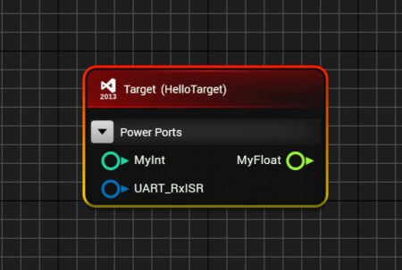
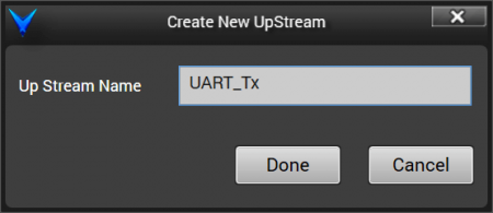
Create an up stream to make the stream communication full duplex. To do this, go into the Target Model Builder and click on the “Up Streams” tab. Right click and click “New” to create a new Up Stream, and name the up stream “UART_Tx”, as shown below. Click ‘Done’, and close the Target Model Builder.
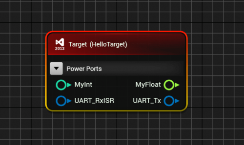
You will note that the target schematic component now has input ports for MyInt and the UART_RxISR input stream, and output ports for the MyFloat and UART_Tx output stream. These ports are ready to be connected to other components as needed for direct interfacing with the target, just like any other host component.
Look at the TargetModel.cs file and verify that the UART_Tx stream source interface read-only property has been added to the target model, as shown below. This is referred to as an “Up Stream” that streams data up from the Target to the Host.

Now in the Target project, open the “Virtuoso.h” header file under the “VirtuosoCore” folder. You will notice a handful of Virtuoso API functions as well as a hUART_TX symbol definition that was rendered by Virtuoso:

To write to this stream on the target side, define a UART TX function in the HW.h to add a logical hardware-independent hardware abstraction interface, as shown below.

Add this function’s implementation to SIM_HW.c, so that it simply calls the Virtuoso API function ‘WriteBufferToVirtuosoUpStream’ to pass the data into the Virtuoso framework to be forwarded to the target model.

With this in place, a virtualized UART is now able to communicate with a C# host application via a target model. When the C# host code wishes to write data to the target, it can simply pass the data to the down stream component, and the UART_RxISR function will be called in the target. When the target code wishes to write data to the host, it can simply call its standard hardware abstraction API function, UART_TX. Inside the SIM_HW implementation of the virtual UART, the UART_Tx function simply forwards the data on to the Virtuoso framework, specifying which UpStream handle should be used. The data then is provided to the C# up stream component and consumed by the C# host application.
We can see that this is all working by adding a simple loopback. Add the code below in the UART Rx ISR to print the string “Byte Received” any time the Rx interrupt is received.

Now in the schematic editor, drag and drop two console terminals, and connect OutStream1 of one terminal to UART_RxISR, and connect UART_Tx to InStream1 of the other terminal, as shown below. For the input console terminal, make sure the “Display OutStream1” checkbox is checked, so that manually typed data transmitted to OutStream1 is displayed.

Reposition the console terminals in the main view as shown.
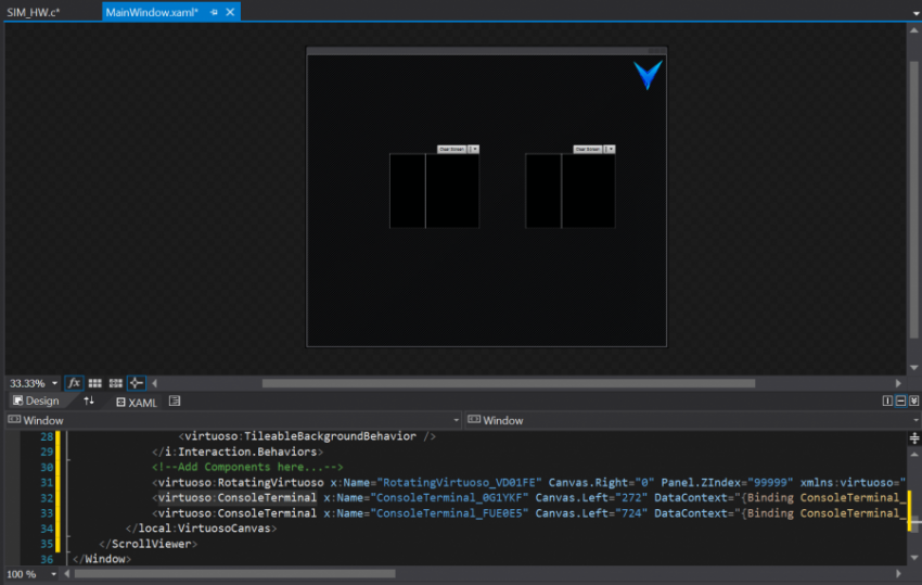
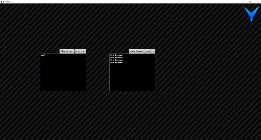
When we build and run the application, when we type into the input terminal, we see the “Byte Received” string printed to the output terminal.
