
Virtuoso Documentation
New Project Creation Guide
In this section, you will set up a new virtual device project from scratch. The full step by step video for the New Project Creation Guide can be viewed below.
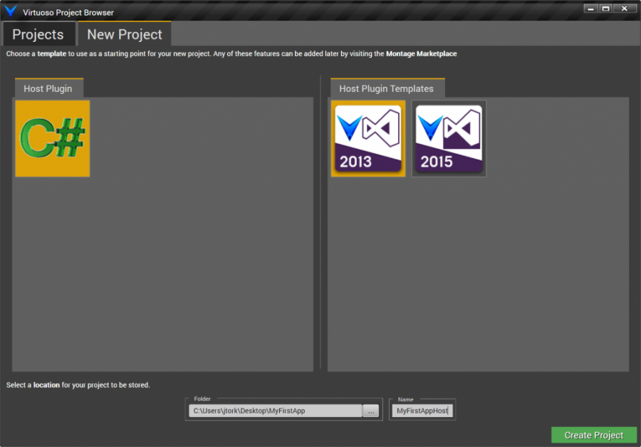
Begin by running Virtuoso directly, either by double-clicking the Virtuoso desktop icon or by running Virtuoso in the Programs taskbar. This opens the Project browser, as shown below. Click on the New Project tab and select C# as the Host Plugin and Visual Studio 2013 as the Host Template. The Host Plugin is the extensible component that provides all Virtuoso related functionality specific to a particular host type, in this case C# WPF desktop applications. The Host Template contains the functionality available out of the box when creating a new host and specifies things like IDE version. Specify the folder and name of your host at the bottom and click the Create Project button.
Your host will be created, and you will see an empty schematic editor window.
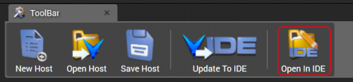
Click the “Open In IDE” button to view your host in its native IDE.
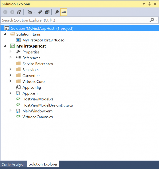
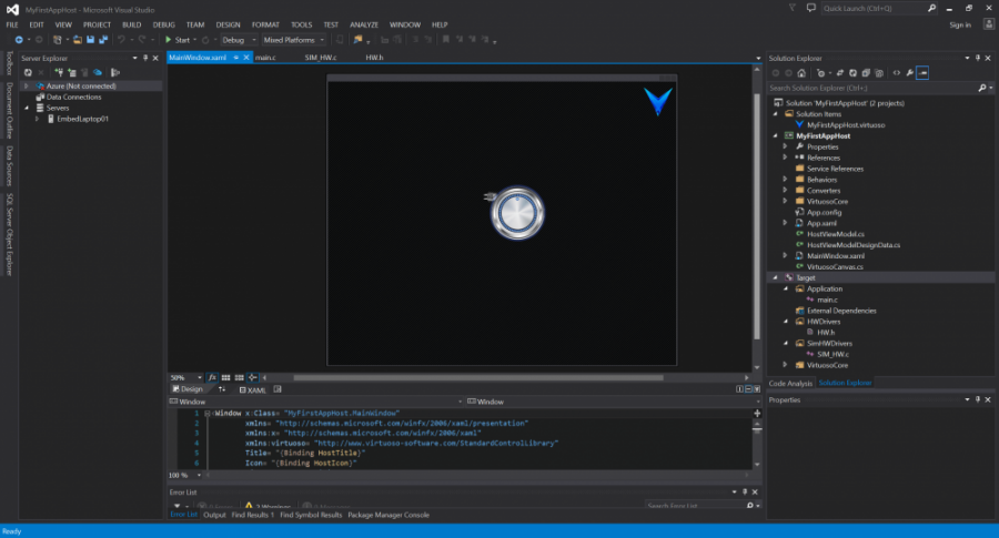
This results in your MyFirstAppHost Visual Studio solution being opened Visual Studio Community 2013, with its MyFirstAppHost C# project. The project is preconfigured as a WPF desktop application with an MVVM implementation.
Build and run the solution. You will see an empty window with the rotating Virtuoso crystal. Stop the host application and return to the schematic editor. You can leave Visual Studio open if you like.
On the left you will see the host component toolbox, as shown below.
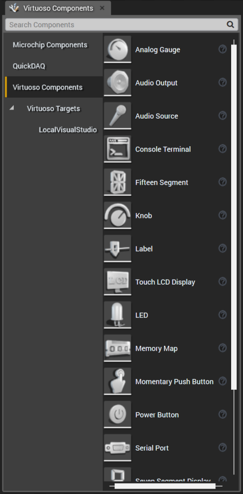
If you have the Embedded Target package installed, you will see a Virtuoso Targets toolbox category, and inside it empty target templates for Visual Studio 2013 and 2015. Drag and drop the target corresponding to the Visual Studio version you have installed onto the schematic editor. You will be prompted to enter the name of the target as shown below. If you plan on only having a single target, using the default “Target” name is suggested, but you can rename it to something more specific to your application if you like. If you plan on hosting multiple virtual microcontrollers, you will need to provide different names.
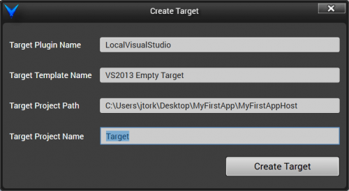
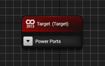
Click “Create Target”. The corresponding C project will be created and added to your host. The host schematic component will be shown on your schematic, initially just a simple component.
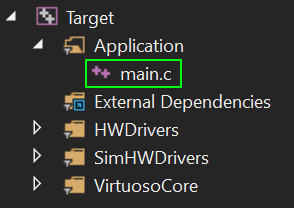
Save the host schematic and then push the changes to the IDE by clicking the “Update To IDE” button. This will result in the host C# application being updated with changes made to the host schematic. Open the host in Visual Studio by clicking the “Open In IDE” button and note that you now have a C# project and a C/C++ project in your solution. Open the main.c file in your target project, as shown below.
The host has a filename extensions of .virtuoso, and is shown in the Visual Studio solution explorer. You can double-click on the .virtuoso file in Visual Studio to open the host in Virtuoso, if you only have Visual Studio open but need to make a change to the schematic.
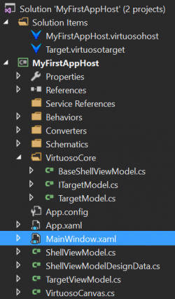
For our new project, we will add an analog input and a digital output and write some application code to use our I/O, to show the basic virtualization concepts. First, expand the Target tree view in the solution explorer, and you will see that there are some files and folders created for you by default.
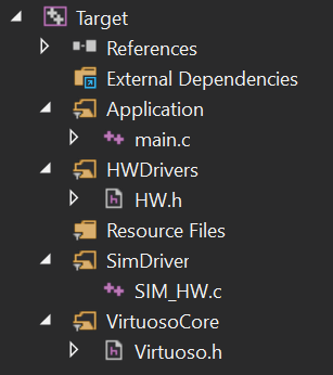
The HW.h and SIM_HW.c are essentially empty, and provided as a place to start quickly building a driver layer. We will open HW.h and define our hardware abstraction layer for a 10-bit ADC and an LED driver as shown below.
#ifndef HW_H

#define HW_H

#ifdef __cplusplus

extern "C" {

#endif


    unsigned short HW_GetADC(void);

    void HW_SetLEDState(unsigned char State);


#ifdef __cplusplus

}

#endif

#endif  // HW_H
Regardless of whether we are building our application in the virtual device or compiling it to run on the physical target hardware, the application will include this header file. The header file should always be the same. We will assume that the actual C source code file for our virtual driver will be a different file than the physical driver, although they could be the same file. Since SIM_HW.c is available to correspond to HW.h, we’ll open that and write our virtual driver.
Open SIM_HW.c and add the virtual drivers as shown below.
#ifdef __cplusplus

extern "C" {

#endif


#include "HW.h"


    unsigned short SIM_ADC = 0;

    unsigned short HW_GetADC(void)

    {

        return SIM_ADC;

    }


    unsigned char SIM_LEDState = 0;

    void HW_SetLEDState(unsigned char State)

    {

        SIM_LEDState = State;

    }


#ifdef __cplusplus

}

#endif
All we are doing is declaring variables to hold the virtual ADC value and the LED state. When the driver is called, we’re either just returning the internal ADC value or setting the internal LED state variable. We have now written our virtual drivers! Next, open main.c and write the application layer business logic, as shown below. The HW.h header file has already been included in main.c by default.
void main()

{

    #ifdef _WINDOWS

    InitializeVirtuoso();    //This must be the first function called for Virtuoso.

    #endif    //_WINDOWS


    //User code must start from here....


    while (1)

    {

        #ifdef _WINDOWS

        VirtuosoSleep(10);    //Sleep(10) is optional and only needed in computer with low hardware configuration. It can be deleted by user.

        #endif    //_WINDOWS


        if (HW_GetADC() > 512)

        {

            HW_SetLEDState(1);

        }

        else

        {

            HW_SetLEDState(0);

        }

    }

}
We can now build and then run the solution. If we set a breakpoint at main, we will be able to step through the virtual driver and see it accessing the variables, but this will not be a very impressive virtual device. What we need to do is extend the model for our target, and then add view components to bind to the model in the host.
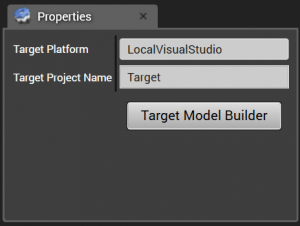
To modify the model for the virtual device, stop the application and then select the target component in the host schematic by left clicking it. NOTE: If you haven’t built your solution yet after adding your variables, you need to build your solution first. In the Property window, you will see the properties for your target. Click on the “Target Model Builder” button to run the target model builder, which will modify your target.
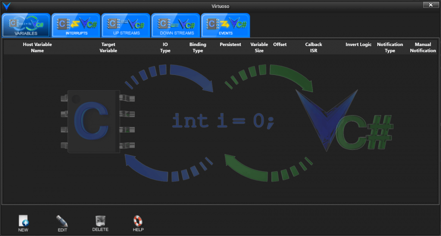
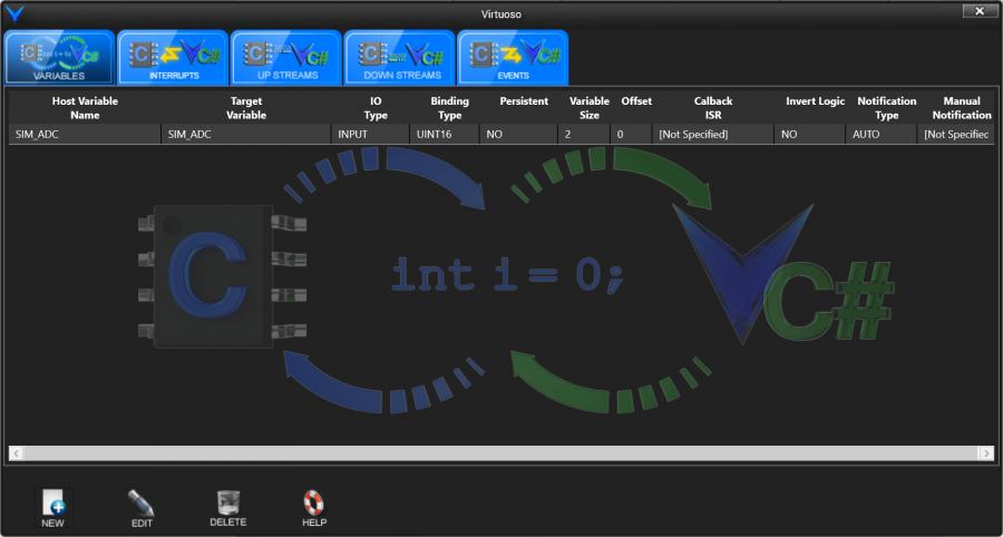
A full treatment of the Target Model Builder is behind the scope of this introductory tutorial. For now, we will just add variables to our target model. When we open the Target Model Builder, we will see the Variables tab, as shown below.
Click on the “New” icon in the lower-left corner, or right click in the tab area and click “New”, to create a new target binding.
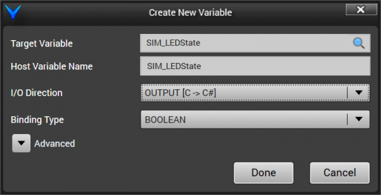
The “Create New Variable” window will appear as shown.
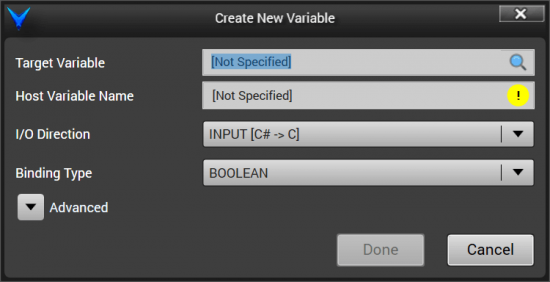
Here, we are creating a variable which will be exposed on the target model in our C# target model class. All statically linked variables in our target will be available to be exposed on the target model, but we can just start typing “SIM” and both of our static variables wlll be auto-filtered.
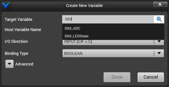
Select the SIM_ADC variable. After selecting SIM_ADC, the Binding Type will automatically change to UINT16, as shown below.

Click Done. You will now see the SIM_ADC variable added to the Target Model Builder.
Click “New” again to add another variable. This time, select SIM_LEDState. Then change the I/O Direction to Output, and change the Binding Type to BOOLEAN, as shown.
Click “Done”. You will now see both variables in the Variables tab of the Target Model Builder. Close the Target Model Builder by clicking the red close button in the top left corner.
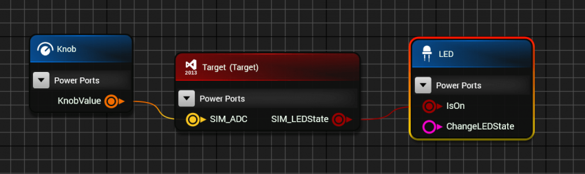
For the moment, we will gloss over what happened with those target model changes; however, you will note that the target component in the schematic editor has been updated with a SIM_LEDState output port and a SIM_ADC input port. All we need to do now is drag and drop an LED and a knob component onto the schematic and wire their ports up, as shown.
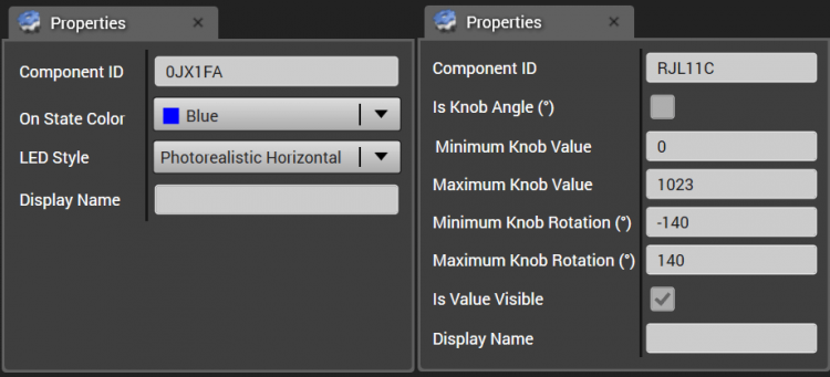
Configure the properties for the LED and the knob as shown below. This configures the LED as a blue LED, and configures the knob component to produce a value from 0 to 1023, with a mechanical limit from -140° to +140°.
Save the host, click “Update To IDE” to push the updates to the host, and open the host in Visual Studio if it’s not open. Expand the C# host project tree view in the solution explorer, and find MainWindow.xaml, as shown below.
Double-click MainWindow.xaml to see the view for the host. If you’re not familiar with WPF applications, you should see the design surface for the view in the top region, and then below that you will see the XAML source code for the view, as shown below.
You will see the LED and knob components on the view. The XAML code for these component views was emitted by Virtuoso, along with the corresponding model and view model objects as properties on the MainWindowViewModel. You can make additional changes to the view components, like resizing and repositioning the controls, and those changes will be retained even when updating the host from Virtuoso. Reposition the components as shown below.

Build and run the project. When you vary the knob using the mouse, you should see the LED turn on and off as you cross the 512-count center point. You have now virtualized hardware!
This first hardware virtualization step has been a functional composition using user interface components. Communication oriented components or even just host C# classes could also be used to interact with the target model in order to virtualize the hardware. It all depends on what you are trying to accomplish with your virtual device.
With a functional analog input and digital output, we were able to develop and test our application layer code. The next step for product development might be to reskin the view to be a photorealistic virtual device that looks exactly like the product being designed. Using the Model-View-View Model design pattern (which hasn’t been fully discussed), it is easy to re-skin a view, which has a specific logical function but may have many ways of visualization.
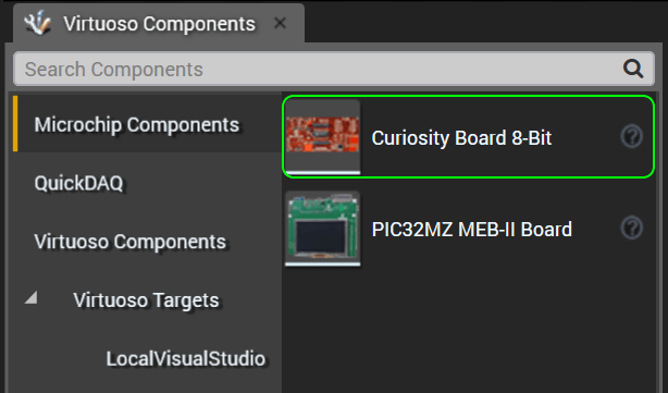
To demonstrate this, we will complete the New Project Creation Guide by reskinning the view to be photorealistic. Remove the LED and knob by deleting the components in the schematic editor. The Curiosity Board can be found in the Virtuoso Microchip Control Library, as shown below. If you haven’t installed the Curiosity Board library, you can find it here.
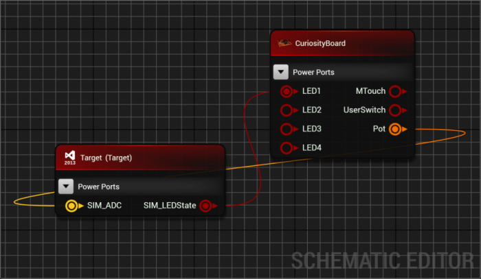
Drag and drop the curiosity board onto the host schematic and connect it to the target as shown below. The Curiosity Board’s analog potentiometer output connects to the SIM_ADC input, and the SIM_LEDState output from the target connects to LED1 on the Curiosity Board.
Push the changes to the host, and resize and reposition the curiosity board, as shown below.
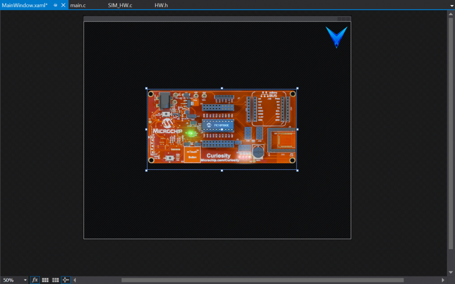
Build the solution, and then run the host. You should now be able to use the potentiometer on the Curiosity board to control LED 1. The function of the virtual device is the same, we’ve just reskinned it to look more like a real product.
This New Project Creation Guide should have given you a good feel for the hardware virtualization concepts.